Graphical Aids
Here you find information about the following topics:
- Toggle Grid
- Snap to Grid
- Set Zoom Factor
- Undo
- Redo
- Change Size of Drawing Area
- Insert Object
- Select Object
- Select Multiple Objects
- Move Objects
- Copy Objects
- Delete Objects
- Find Objects
- Toggle between Entered and Calculated Data (in System Diagram)
- Change Font of Selected Objects
- Change Diagram Font
Toggle Grid
- On the Diagram toolbar, activate/deactivate
 .
.
Snap to Grid
When you insert objects, you can choose whether you want to adjust them automatically to the grid or not.
- On the Diagram toolbar, activate/deactivate
 .
.
Set Zoom Factor
- On the Diagram toolbar, click
 to choose the zoom factor from
the drop-down list, or enter a value manually and press ENTER.
- On the Diagram toolbar, click
 or CTRL+F12 to zoom into the
diagram step by step.
- On the Diagram toolbar, click
 or CTRL+F11 to zoom out of the
diagram step by step.
Undo
- On the Diagram toolbar, click
 .
.
- Press CTRL+Z.
Note:
- You can undo only the shifting and resizing of objects on the Drawing Area.
Redo
- On the Diagram toolbar, click
 .
.
- Press CTRL+Y.
Note:
- You can redo only the shifting and resizing of objects on the Drawing Area.
Change Size of Drawing Area
- Select an object and drag it over the system boundary. The size of the Drawing Area will be adjusted dynamically.
- Move the handle at the end of the rulers of the Drawing Area.

Insert Object
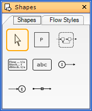
- On the Shapes window, click an object symbol (process, flow, text field, system boundary).
- On the Drawing Area, click the position where you want to insert the object with a predefined size.

Note:
-
After inserting an object, the edit mode is activated. Press SPACE to reactivate the last object-inserting mode.
Select Object
- On the Shapes window, click
 to switch to the edit mode.
- On the Drawing Area, click an object.
Select Multiple Objects
- On the Shapes window, click
 to switch to the edit mode.
- On the Drawing Area, click an object.
- Hold CTRL while clicking other objects.
or
- On the Shapes window, click
 to switch to the edit mode.
- On the Drawing Area, erect a frame around the desired objects (drag-and-drop). All objects lying within or cut by the frame are selected.
Move Objects
- Select objects.
- Drag one of the selected rectangular objects to its new position.
Copy Objects
- Select the objects you want to copy.
- Press CTRL+C or choose Copy in menu Edit to copy objects
- Press CTRL+V or choose Paste in menu Edit to paste objects.
- Drag copied objects to the desired position.
Note:
- If copied objects are inserted into a different STAN file, data will be considered only if fitting periods and layers exist.
- Already existing names and short symbols will be assigned an index.
Delete Objects
- Select an object.
- On the Diagram toolbar, click
 or press Delete or choose
Delete in the context menu (right-click) of the object.
- Confirm the warning.
Note:
- In the appearing warning, you can select that these kind of warnings shall not be displayed any more in the future. This can be undone only by resetting the application to default settings.
Find Objects
- On the Edit menu, select Search in model.
- On the Data Input toolbar, click
 .
.
- Press CTRL+F.
Then
- Enter a search term, select the fields and elements to be searched and click Search.
- Select the desired object from the appearing list in the Trace Output window.
- If not needed anymore, close the Search window.
Note: The selected object will be highlighted in the System diagram. If it is an internal part of a subsystem, a new window will be opened.
Toggle between Entered and Calculated Data (in System Diagram)
In the System Diagram, either entered or calculated data can be displayed.
- If you see
 in
the Sankey toolbar, calculated (= output) data will be
displayed in the System diagram.
- If you see
 in the
Sankey toolbar, entered (= input) data will be displayed in
the System diagram.
- You can toggle between these two states by clicking
 or
or  respectively.
Change Font of Objects
- Select the objects where you want to change the font.
- Choose Font from the context menu (right-click) or
 in the Diagram toolbar.
- Choose the desired settings in the Font dialog.
- Confirm by clicking OK.
Change Diagram Font
- On the Extras menu, select Options, then tab Common.
- Click
 .
.
- Choose the desired settings in the Font dialog.
- Confirm by clicking OK.
Note:
- In the appearing warning, you can select if these settings should be applied to all existing (= yes) or only to new objects (= no).